Measurement tool reference
Use the Measurement tool to take measurements of your model.
To access the Measurement tool, click Measure in the main toolbar. Alternatively, on the Tools pane, select Measurement.
Type of Measure section
Choose a measurement mode:
|
Mode |
Examples of use |
|
One click |
Take measurements from a single geometry. For example, you can measure segment lengths and circle circumferences. Read more. |
|
Two clicks |
Take measurements from two geometries. You can also measure acute angles between planes. Read more. |
|
Advanced |
Take measurements from geometries that are not available using the other modes. |
Detection Mode section
Choose a detection mode:
|
Type |
Description |
|
Edge / Segment |
A segment or an edge with two endpoints, such as an arc. |
|
Circle |
A complete circle. |
|
Object |
A part. |
|
Plane |
For a surface, the tangent plane at the selected point. For a line, the perpendicular plane at the selected point. This detection mode is available only with the two-clicks and advanced modes. |
|
Point |
The selected point on the model. This detection mode is available only with the two-clicks and advanced modes. |
After you have chosen a detection mode, select a primitive in the viewer. When you hover over the model, the pointer changes color depending on whether you hover over a primitive of the selected type.
Primitives section
This section is displayed only for the advanced mode.
This section shows the primitives that you have created using the advanced mode.
To take measurements or create primitives, select primitives in the list and right-click. Alternatively, in the viewer, select a geometry. Depending on your selection, the primitive shortcut menu shows some of these options:
|
Option |
Description |
|
Make measurement |
Take measurements of the selected geometry. Tip: Before choosing a measurement, hover over the list to highlight measurements in the viewer. |
|
Construct primitive |
Build a primitive from other primitives. For example, you can create a segment that joins several segments, then measure its total length. From two circles, you can draw a line that goes through the circle centers, then measure angles. |
|
Convert into |
Convert the selected primitive into a primitive of another type. For example, from a circle, you can create a line that is the circle revolution axis or create a point at the center of the circle. |
|
Create […] primitive |
Create the selected primitive. |
|
Cancel |
Cancel the selection. |
To view the primitives on which a primitive is based, expand the primitive node.
To delete all primitives from the list, click Clear primitives. You can't delete primitives one by one.
After you have taken measurements, the primitives list is cleared.
Measurements section
The Measurement section lists the measurements that you have taken.
Right-click an item in the list to perform actions from the shortcut menu:
|
Mode |
Menu option |
Description |
|
One click Two clicks |
Fit view |
Fit the view to the measurement Note: Using the Fit view button on the main toolbar or by pressing F, you can fit the view to the model, but not to the selected measurement. |
|
Rename |
Rename the measurement |
|
|
Delete |
Delete the measurement |
|
|
Show all |
Show all measurements in the viewer |
|
|
Hide all |
Hide all measurements in the viewer |
|
|
Delete all |
Delete all measurements |
|
|
Align tag to view |
Align the tag of the selected measurement with the view |
|
|
Align all tags |
Align all tags with the view |
|
|
Advanced |
Reuse primitive(s) |
Reuse the selected primitives |
|
Delete measure(s) |
Delete the selected measurements |
From the measurements list, you can also perform these actions:
- To show or hide measurements and primitives in the viewer, select or clear their check boxes.
- In the advanced mode, to view the primitives on which a measurement is based, expand the measurement node.
Properties section
The Properties section lists the measured dimensions, in millimeters, for the selected measurement:
|
Measurement type |
Measured dimensions |
|
Edge or segment |
Length Projected length on the X, Y, and Z axes |
|
Circle |
Radius Diameter Area Coordinates of the center Coordinates of the vector of the revolution axis |
|
Object |
Area Volume Coordinates of the center of the bounding box Coordinates of the minimum bounding box and the maximum bounding box |
|
Angle |
Angle |
|
Between two primitives |
Minimum distance Projected distance on the X, Y, and Z axes |
Select a dimension to highlight it in the viewer.
NOTE The Properties section shows exact dimensions, but the viewer shows, by default, rounded dimensions. You can turn off the rounding of dimensions for the viewer. To do this, turn off the AutoMeasurementUnit setting in the user preferences. Read more.
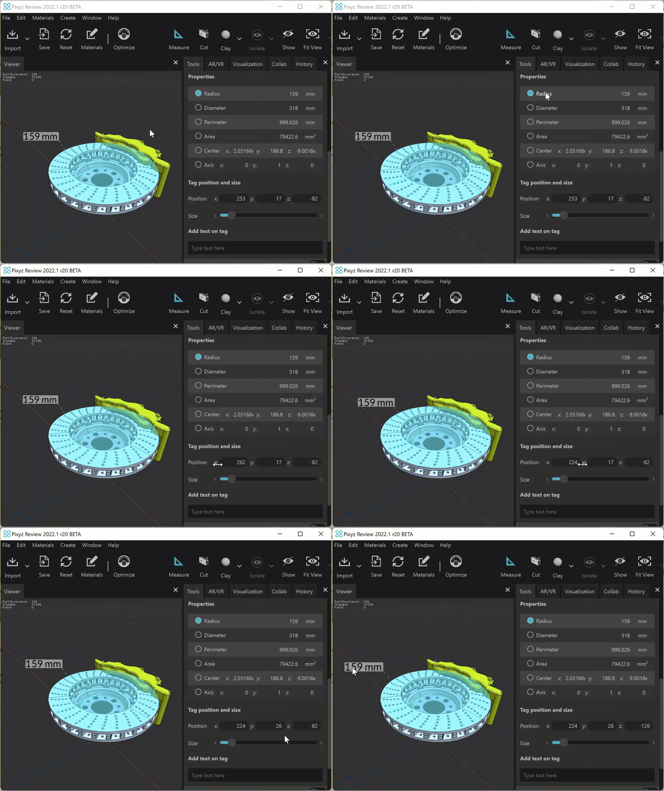
Tag position and size section
This section shows the properties of the tag for the selected measurement property.
You can customize the size, the position, and the text of a tag.
To modify a tag position, enter coordinates in the x, y, and z fields. Alternatively, click the x, y, or z field name and, while holding down the mouse button, drag the cursor to change the coordinate on the selected axis.
From the Measurements section, you can align tags with the view. Read more.
NOTE You can’t select tags in the viewer because these are not added to the product structure.
