Cutting Plane

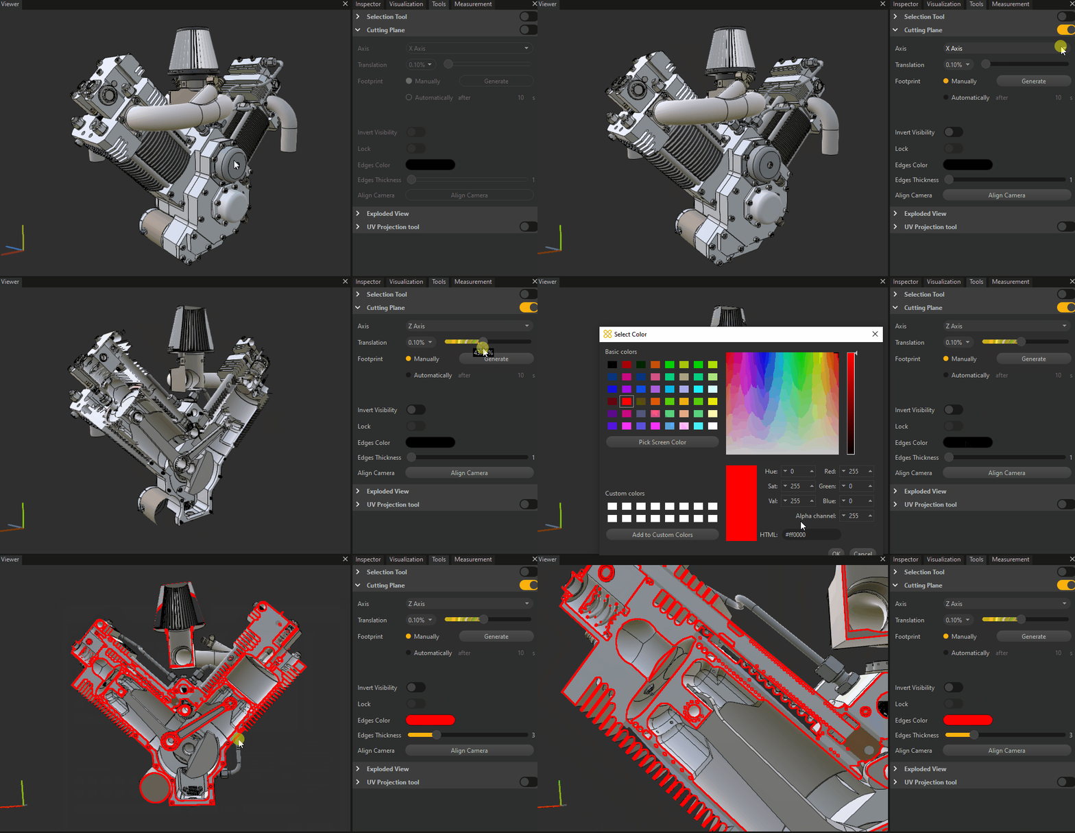
The Cutting plane tool allows you to visualize the internal parts of your models.
When the tool is activated, all parts contained in the scene will be affected by the cutting plane.
Tool parameters
Use the Toggle button to activate the tool.
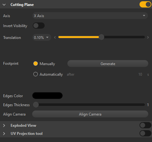
Choose the cutting axis and slide the Translation cursor to move the cutting plane.

The Cutting plane tool comes with a list of parameters to fine-tune the cutting plane.
| Item | Description | |
|---|---|---|
| Axis | Defines the axis of the plane used for cutting the scene parts | |
| Invert Visibility | Defines the direction towards which scene parts visibility is kept. Toggle to invert the direction. | |
| Translation | Translates the cutting plane along the defined axis. The increment parameter defines the translation threshold. TIP: Use the keyboard arrow keys (left/right) to increment the cutting plane position |
|
| Footprint | Allows you to generate a plain cross-section, or footprint, either Manually or Automatically (when enabled a footprint will be automatically created after the time defined by the setting). The generated footprint is created as an occurrence in the Product Structure, where its visibility can be modified or can be deleted. Translating the cutting plane again hides the footprint. | x²x²x²² |
| Edge Color | Defines the color of the generated footprints contour NOTE: Use after generating a footprint |
|
| Edge Thickness | Defines the thickness of the generated footprints contour (in pixels) NOTE: Use after generating a footprint |
|
| Align Camera | Aligns the Viewport camera with the footprint NOTE: Use after generating a footprint. Consider switching to orthographic camera ( P key) |