Tessellate models
API function: algo.tessellate
Use tessellation to transform CAD models into meshes that are ready to be displayed and exported.
CAD models contain precise parametric geometries. For visualization purposes, create meshes from CAD models using tessellation. Tessellated meshes are approximated versions of CAD models. Read more about 3D model types.
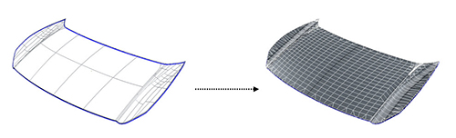
This example shows a CAD model before and after tessellation:
|
|
A mesh is a model that's made up of multiple contiguous polygons. Polygons are usually quadrangles that equal two coplanar triangles. These polygons make up discretized geometries. Mesh geometries can be read by a GPU and rendered in a 3D application.
The more polygons there are, the more realistic the rendering, but the more resource-intensive the computation.
The tessellation phase is essential in the 3D data preparation workflow because it defines the maximum quality of the CAD model.
Parameters
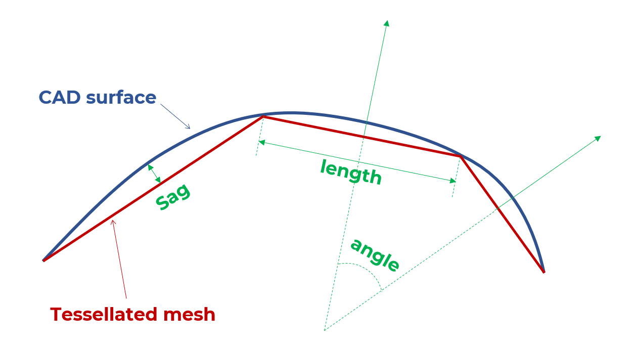
Tessellation parameters are tolerance values:
- The maximum sag between polygons and CAD geometries
- The maximum sag ratio
- The maximum length of polygons
- The maximum angle between the normals of polygons
Use these parameters to balance visual quality and the polygon count according to your needs.
Maximum sag
This parameter is the maximum distance between a CAD geometry and a mesh geometry, in millimeters.
The maximum sagitta (sag) is also referred to as chord error.
Use this parameter to control how close the approximated mesh geometries are to the precise geometries of the original CAD surface.
The lower value, the finer the mesh.
In this example, the mesh is less rough and more realistic with a maximum sag of 0.1 mm than with 0.2 mm:
The maximum sag is a distance criterion. For small parts, use a small value to create enough polygons. For bigger parts, you can also set a small value to preserve quality in areas that contain important details.
Sag ratio
This parameter is the maximum distance ratio between a CAD geometry and a mesh geometry, in millimeters.
Maximum angle
This parameter is the maximum angle that's allowed between each normal of two adjacent polygons, on the same face.
This parameter provides more precision on fillets that have a small radius.
Adjust this parameter to create enough polygons in highly curved areas whose radius is lower than the maximum sag, such as fillets.
For example, for a model that has flat and curved areas, assess this parameter with the maximum sag. If you set a lower value for the maximum sag, then curved areas are better shaped and the number of polygons increases only in these areas.
In this example, the fillet precision is better with a maximum angle of 20° and a maximum sag of 0.2 mm:
Example: maximum sag versus part size
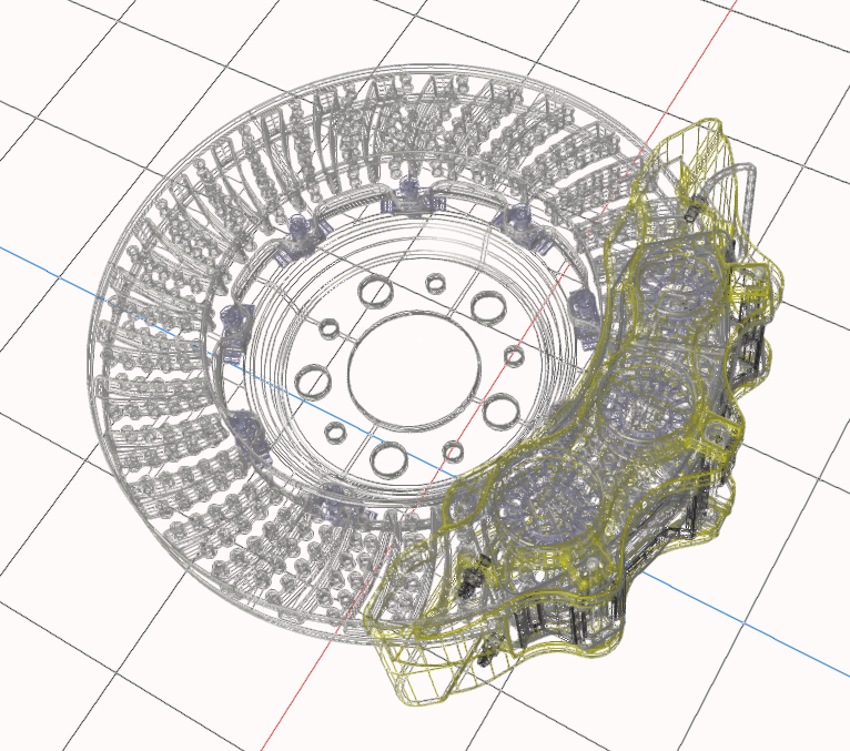
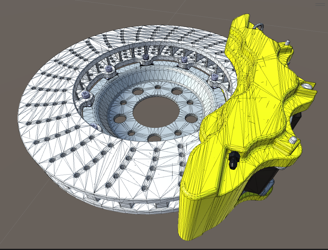
In this example, a model has two parts:
- A red beam that's tessellated with a maximum sag of 5 mm
- A ring that's tessellated with a maximum sag of 0.1 mm
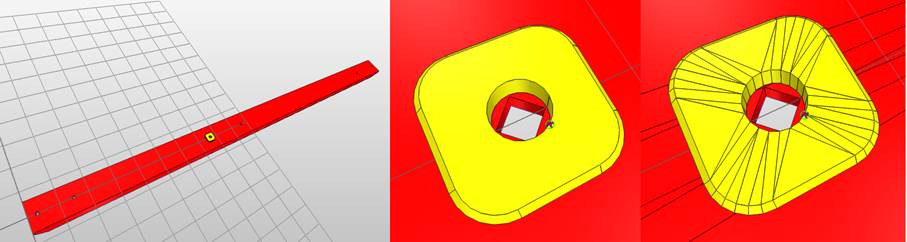
Tessellation results in a loss of details on the beam. The hole in the beam, beneath the ring, turns into a square.
This example illustrates the importance of the maximum sag tolerance for tessellation. The size of each of part isn't taken into account.
However, you can set tessellation parameters based on part size. To do this, you can, for example, create a script that targets the size of the bounding box of the parts.
Maximum length
This parameter is the maximum length of a polygon, in millimeters.
We recommended that you don't use this parameter if you tessellate a model only for rendering purposes. The reason is that a low value may result in an unnecessarily high polygon count.
Use this parameter with very long objects, such as plane bodies and train cabins, because polygons that are too long may cause lighting artifacts.
Best practices
In general, the best strategy is to determine the appropriate criteria for your needs, for example the size, the materials, and metadata. Then, perform a targeted tessellation based on the defined criteria.
For example, to give to shiny aspect to a car body, use fine tessellation parameters to allow for sharp light reflections.